
Deploy and Configure Azure Firewall and Rules to Allow/Deny Access to Certain Websites
Deploy and Configure Azure Firewall and Rules to Allow/Deny Access to Certain Websites
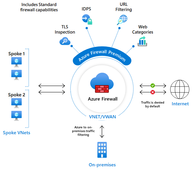
The Azure Firewall is a fully managed cloud-native service that provides network security to protect your Azure virtual network resources. The service offers built-in high availability, unrestricted scalability, threat intelligence-based filtering, logging and monitoring, and many more features and capabilities.
Azure Firewall offers Layers 3–7 connectivity policies and is offered in three SKUs , for which throughput and enabled features depend on which SKU you deploy and is subject to different pricing: Standard , Premium, and Basic . It can be deployed on any virtual network, but is typically deployed on a central virtual network (VNet), such as a Hub-VNet where we peer other virtual networks to it in a Hub-and-Spoke model. It can also be integrated to use third-party security as a service (SECaaS) providers.
Use Cases
While there are many different use cases for using Azure Firewall for protection from incoming and outgoing threats by controlling and monitoring internal and external access to our networks, here are a few examples:
- Force tunneling all Internet-bound traffic to a designated next hop for inspection instead of going directly to the Internet
- To restrict and monitor traffic between partners and the SaaS platform
- Locking down outbound traffic from an App Service Environment
- Secure ingress and egress traffic between an Azure Kubernetes Service (AKS) cluster and external networks
- Filter network traffic between subnets (east-west) and application tiers (north-south)
- Detect and protect at deep levels through packet inspection
- Restrict outbound HTTP and HTTPS traffic based on the FQDN of the destination
How does it work?
Azure Firewall allows us to control and filter traffic through the use of configurable NAT rules, network rules, and application rules using either classic rules or Firewall Policy. Azure Firewall denies all traffic by default, until rules are manually configured to allow traffic.
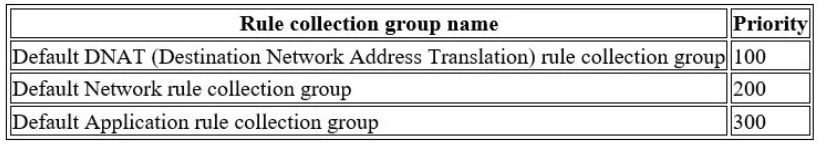
This demonstration will utilize a Firewall Policy for configuring rulesets, which will prioritize and process rules based on the hierarchy listed below by default.
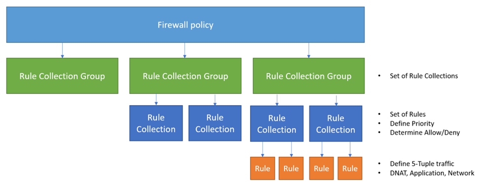
You can read more about firewall rule processing logic on this Microsoft page .
Lab Demonstration
In this demonstration, I will explain the steps for deploying an Azure Firewall in a subnet of a virtual network and creating firewall rules on a firewall policy by completing the following list of tasks:
- Set up a test network environment
- Deploy a firewall and firewall policy
- Create a default route
- Configure an application rule to allow access to www.google.com
- Configure a network rule to allow access to external DNS server
- Configure a Destination Network Address Translation (DNAT) rule to allow a remote desktop to the test server
- Test the firewall
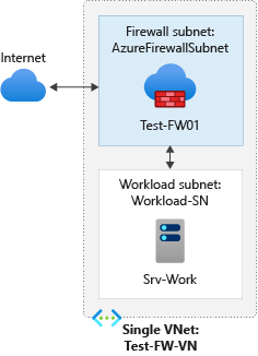
Task 1: Set up a test network environment
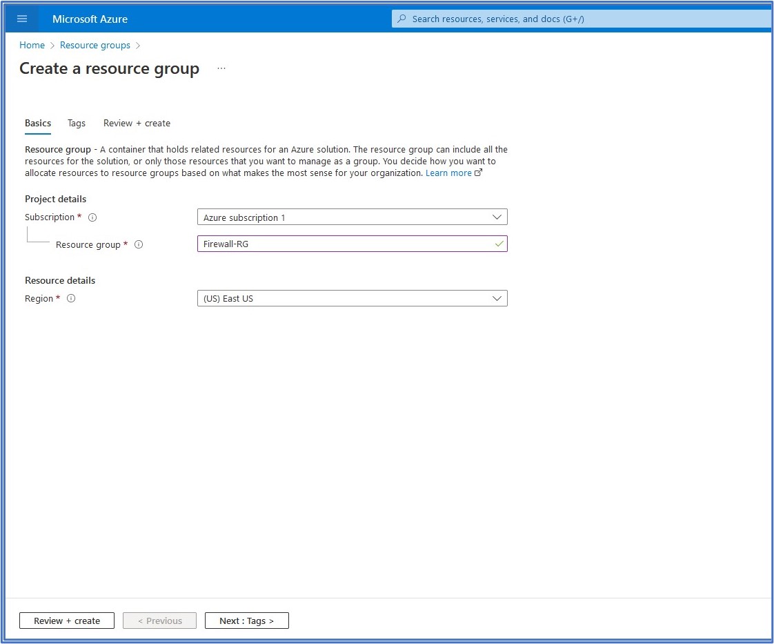
a. Create a resource group
In our first task, we need to create a Resource Group (RG) that will hold related resources for this deployment. In the top search bar, type in resource group and select it from the list of services, then click on + Create to begin the creation process of the resource group. On the Basics tab, we select our subscription, type in a name for the Resource Group, and then select our Region from the drop-down list. Here, I named my Resource Group Firewall-RG and selected East US as my deployment region. Click on Review + create to kick off the deployment of the RG.
b. Create a virtual network and subnets
In the next task, we need to create a Virtual Network (VNet) with the subnet ranges that we will need taken from our VNet address space. In the top search bar, type in virtual network and select it from the list of services. Then, click on + Create to advance to the Virtual Network configuration page.
On the Basics tab, we select our Subscription, Resource group, and Region from the drop-down lists. For the Instance details, we provide a name for the Virtual Network. Then, click on Next: IP Addresses to advance to the next configuration tab.
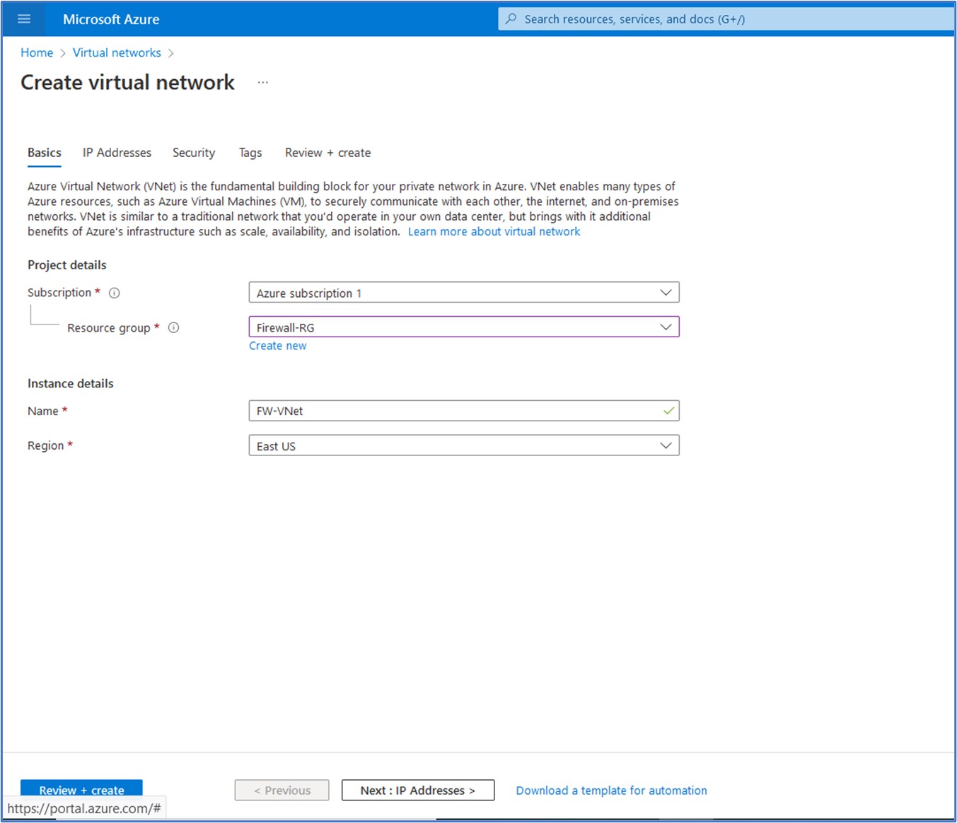
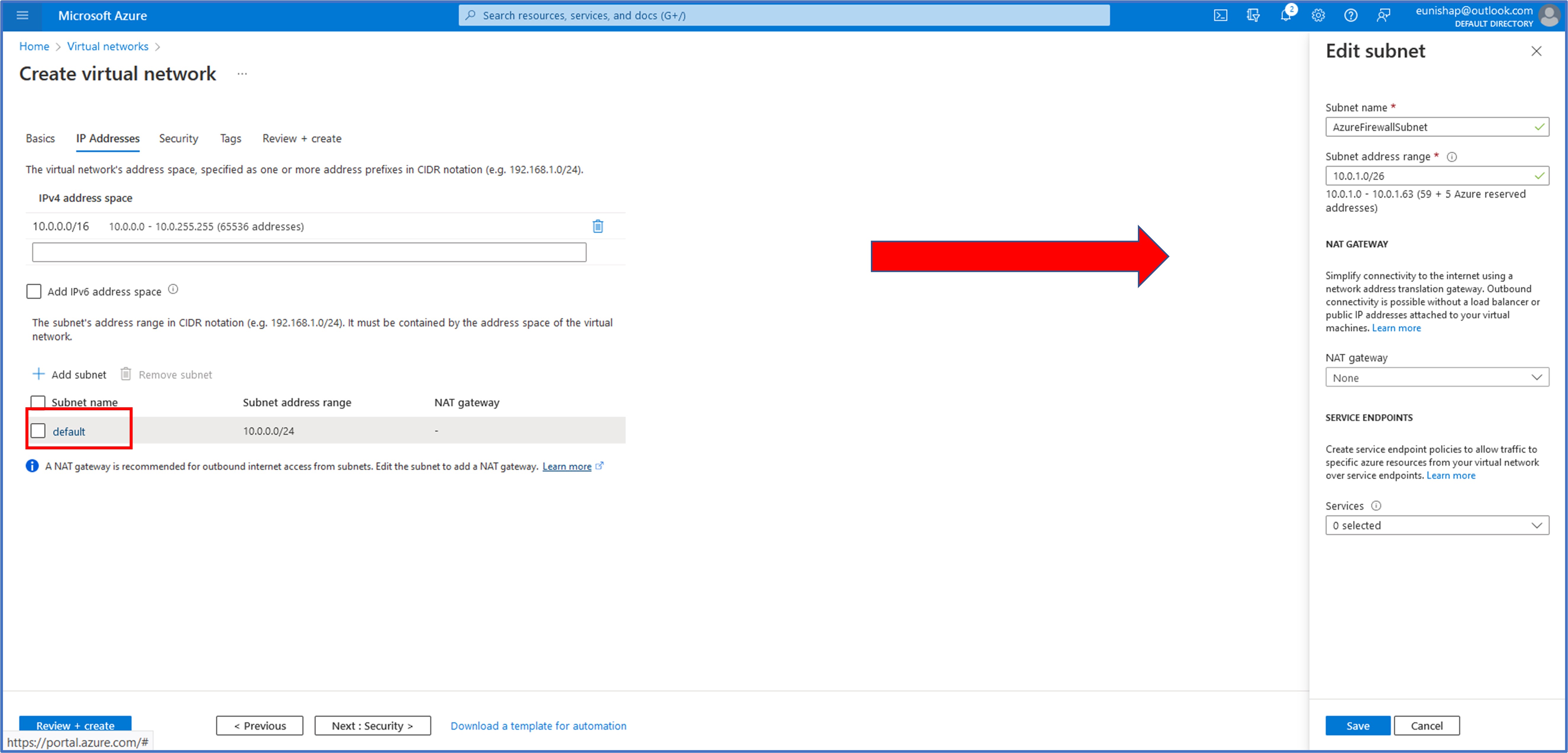
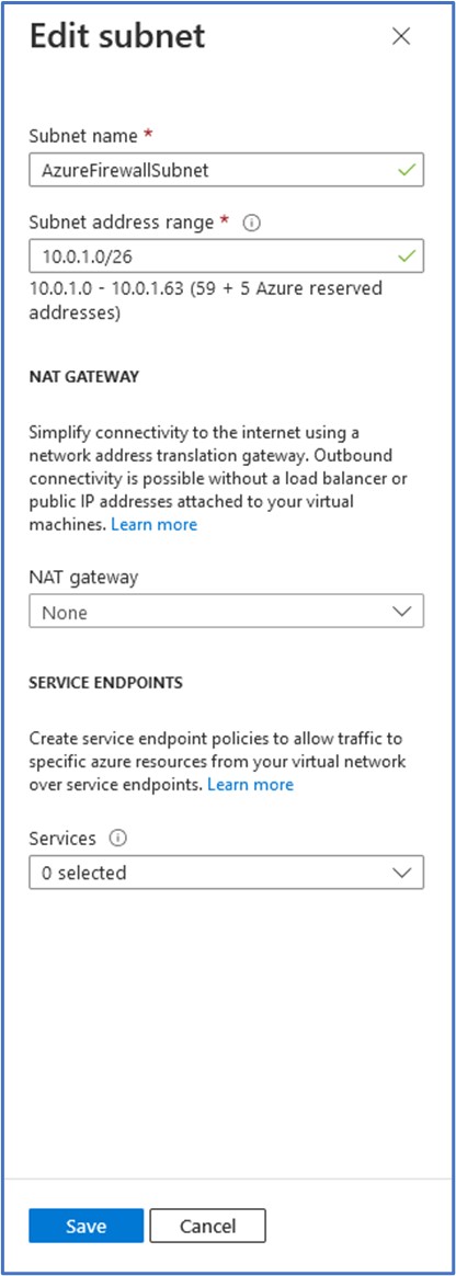
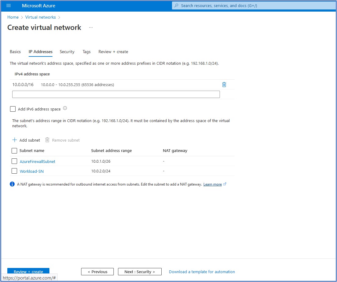
On the IP Addresses configuration tab, we can modify the IPv4 address space for the virtual network. I went with a CIDR range of 10.0.0.0/16. Next, we need to configure the subnets that will be used on this VNet. Click on the “default” subnet below to open a pane on the right that will allow you to edit this pre-existing subnet. The first subnet that we will create is the “AzureFirewallSubnet”. The Azure Firewall (FW) requires a dedicated subnet with a CIDR of at least /26 to ensure that the firewall will have enough IP addresses available to accommodate any scaling. I provided the FW subnet of 10.0.1.0/26. Click on Save to accept the configuration of this subnet. Then, click on + Add subnet to create a new subnet.
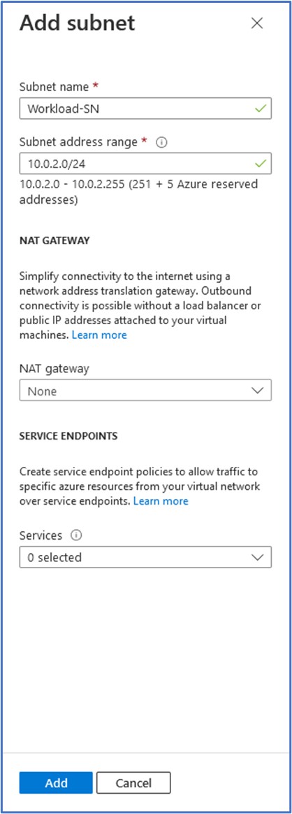
Next, we will add a subnet for the virtual machine that we will deploy into this subnet. Give the subnet a name and an address range. Here, I have entered a subnet address range of 10.0.2.0/24 and a subnet name of Workload-SN. Click on Add to add this subnet to the virtual network.
Next, we can confirm and verify the IP Addresses configuration that we wish to deploy and click on Review + create to kick off the deployment of this Virtual Network if we do not wish to add any additional configuration to it.
c. Create a virtual machine
With our virtual networks deployed and ready, we can now move on to the deployment of the workload virtual machine that will reside on the subnet that was just created. In this step, I used an ARM Template to expedite the deployment of the virtual machine by uploading the template and parameters files to a CloudShell storage on the Azure portal. I then initiated the deployment by assigning the $RGName variable with the name of my RG, Firewall-RG, and then proceeded with the New-AzResourceGroupDeloyment cmdlet.
$RGName = “Firewall-RG”
New-AzResourceGroupDeployment -ResourceGroupName $RGName -TemplateFile firewall.json -TemplateParameterFile firewall.parameters.json
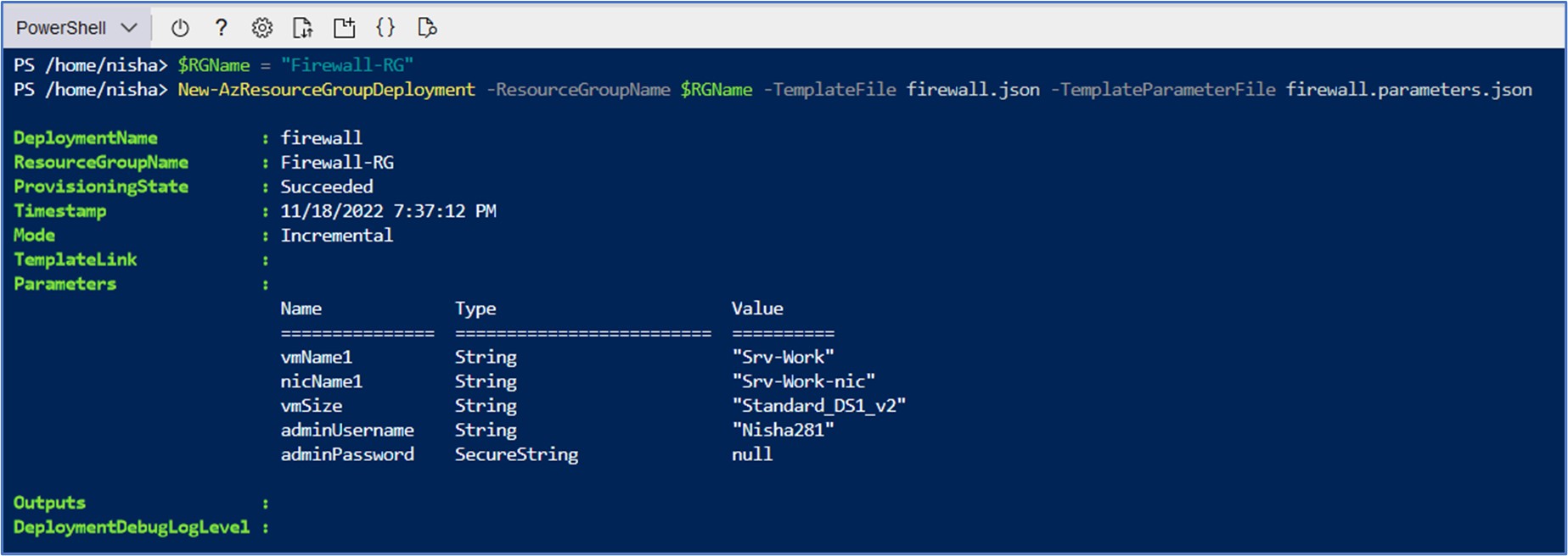
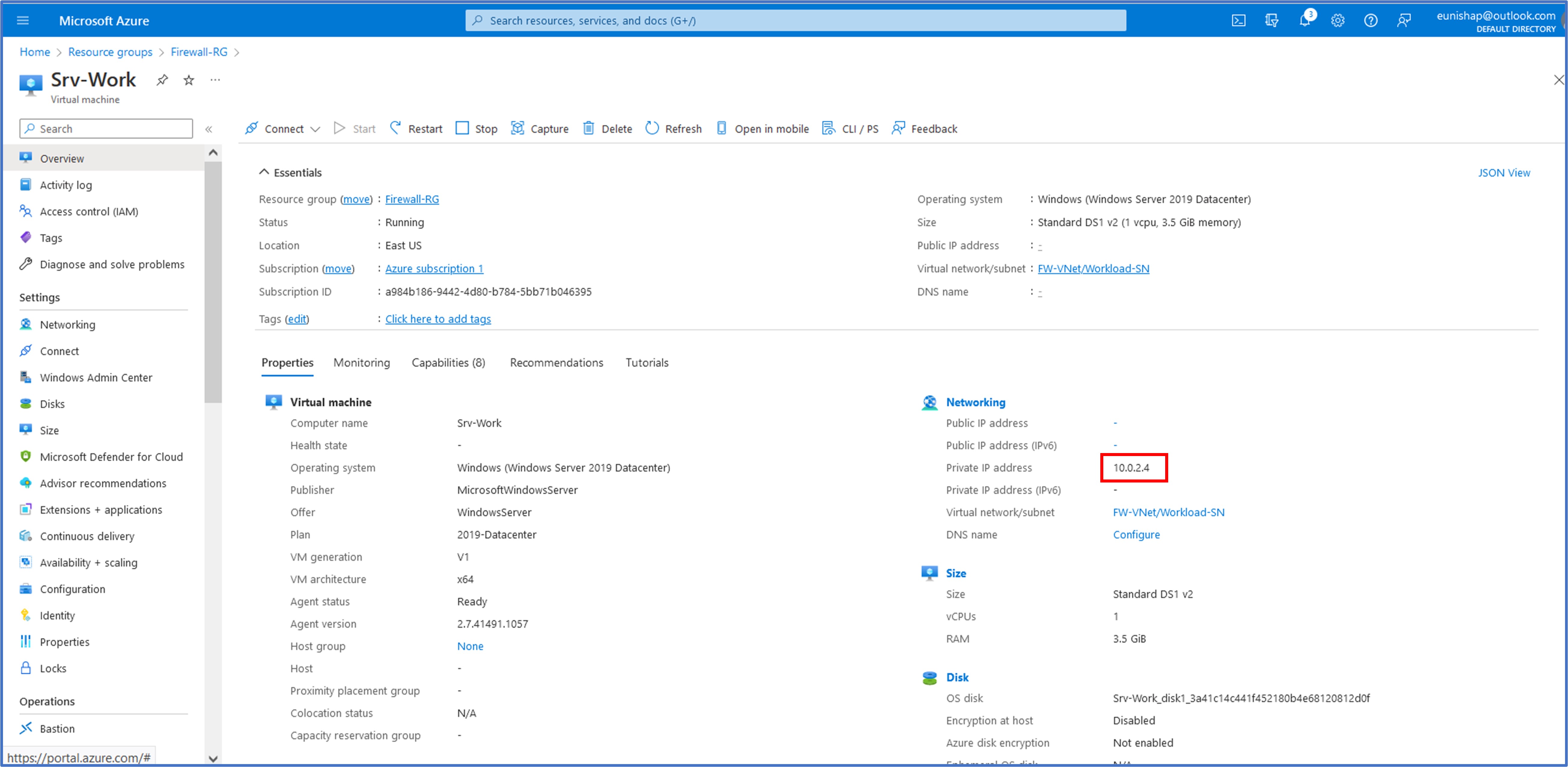
Upon completion of the VM deployment on the Cloudshell, I searched the top bar for virtual machines and clicked on my VM, Srv-Work to verify its assigned IP address, 10.0.2.4.
Task 2: Deploy the firewall and firewall policy
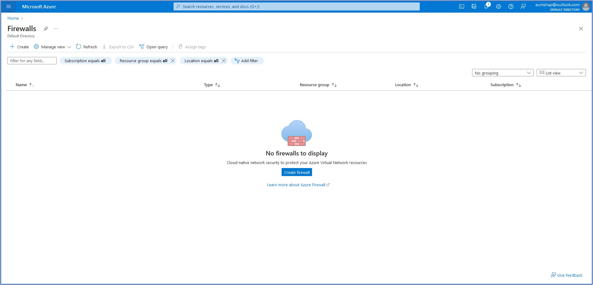
With our virtual networks, subnets, and virtual machines now deployed, we are now ready to deploy the Azure Firewall into the virtual network with a firewall policy configured. In the top search bar, type in firewall and select it from the list of services. Then, click on + Create.
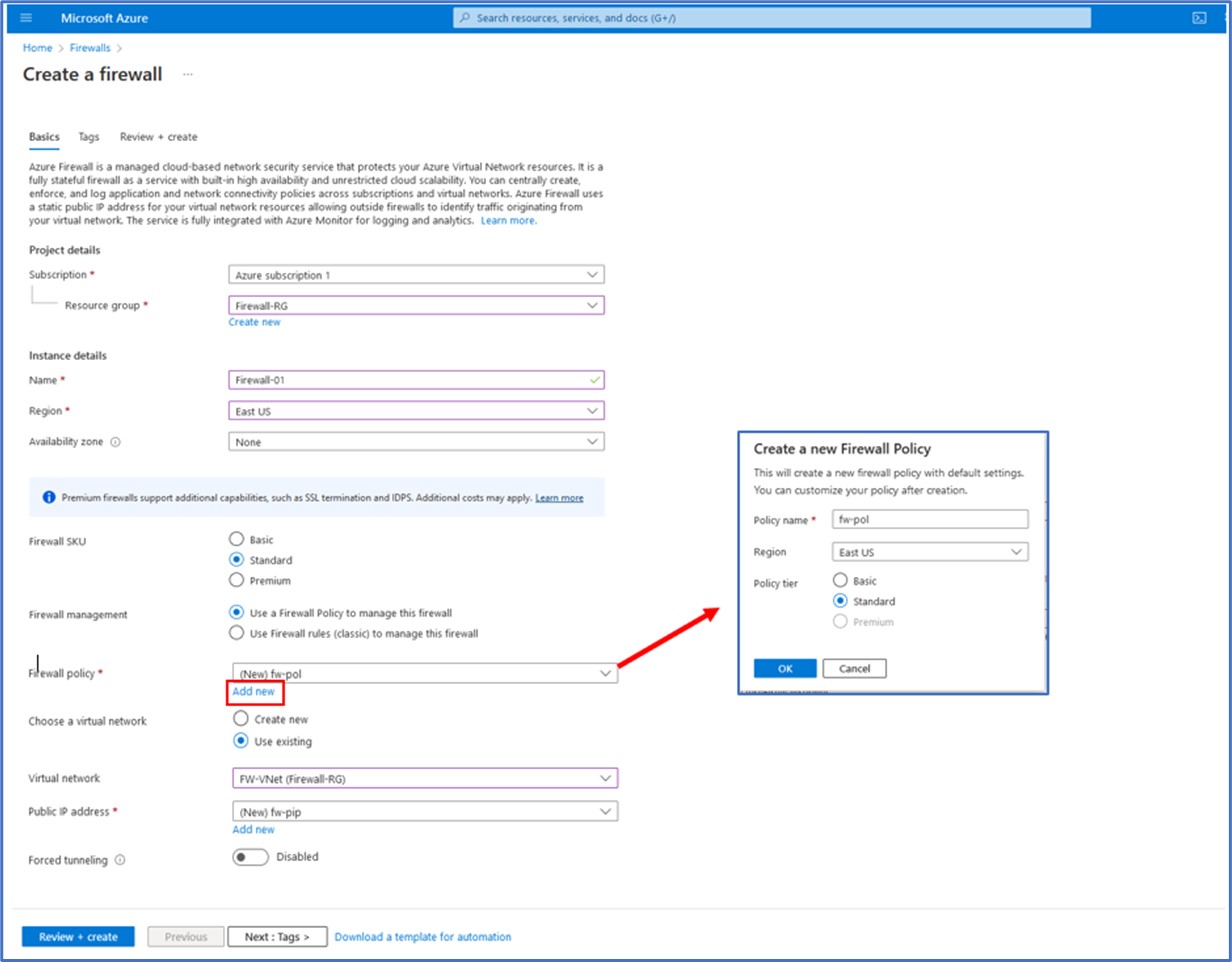
Search for firewall in the services list In the next step, we will provide the information needed to create a firewall for this deployment. To begin, we select our subscription, Resource Group, Region, Availability Zone information, and a name for the firewall instance. Here, I have entered the name of Firewall-01 for this FW, selected a Standard Firewall SKU, and selected the option to use a Firewall policy.
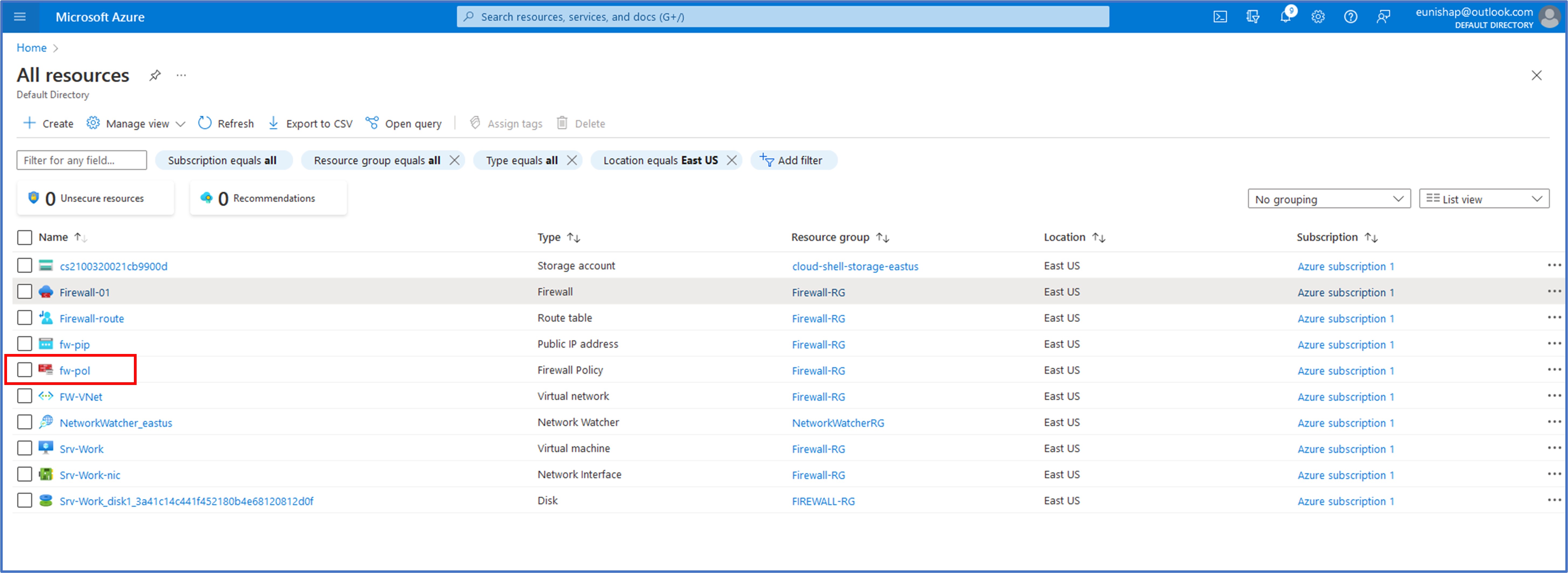
Next, we need to create a new Firewall Policy by clicking on “Add new” and then entering a name, Region, and Policy tier for the FW. Here, I named the policy “fw-pol”, selected the East US Region since this is where my resources have been deployed to and selected a Standard Policy tier.
Finally, we can choose to create a new virtual network for the firewall or choose an existing VNet where it should be deployed to. Here, I selected the FW-VNet that was deployed earlier and created a new Public IP address for the firewall, naming it fw-pip. Forced Tunneling mode is a configurable option that is available for the firewall in the event that we need to force outbound Internet-destined traffic to an on-premises site for inspection prior to routing it to the Internet. While this option will be used in a future demonstration, it was not enabled for this deployment. Next, click Review + create to kick off the firewall deployment process. This process can take up to 30 minutes to complete.
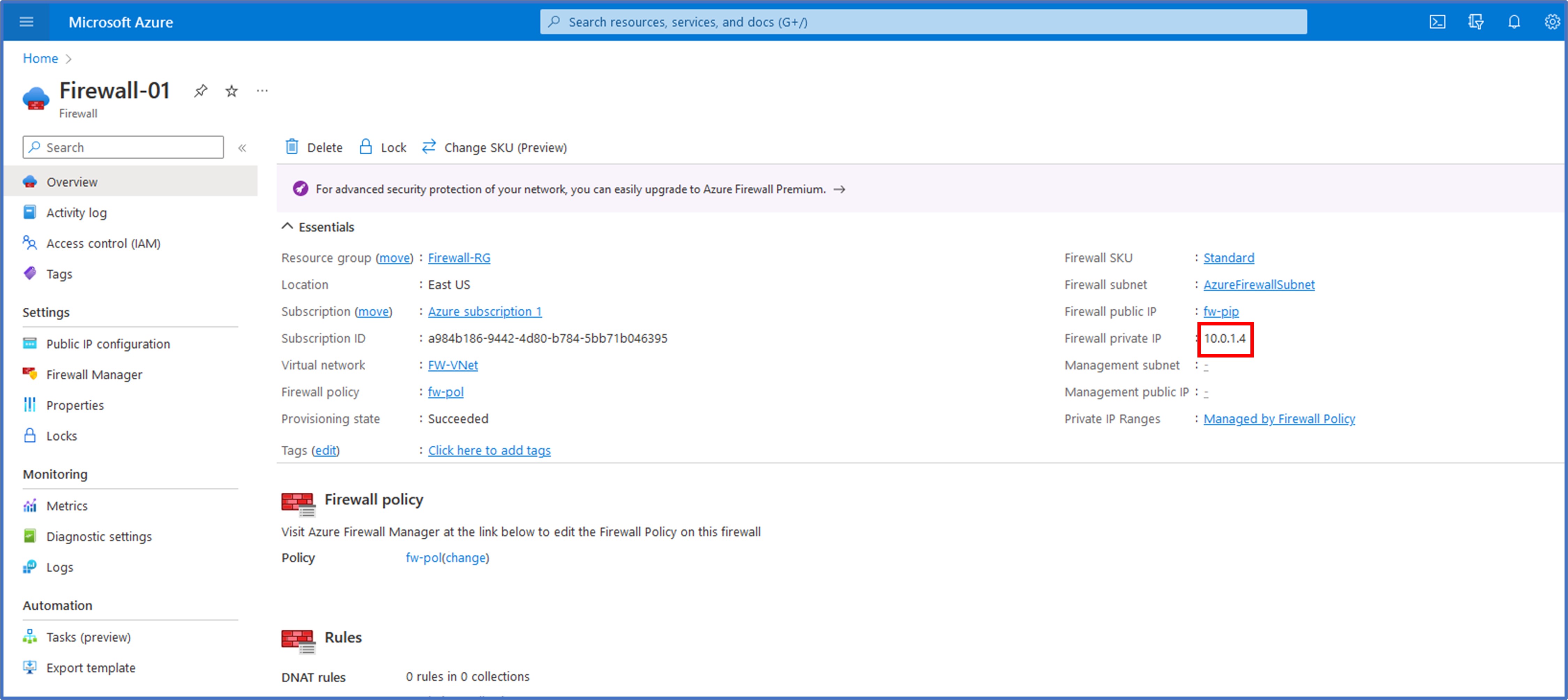
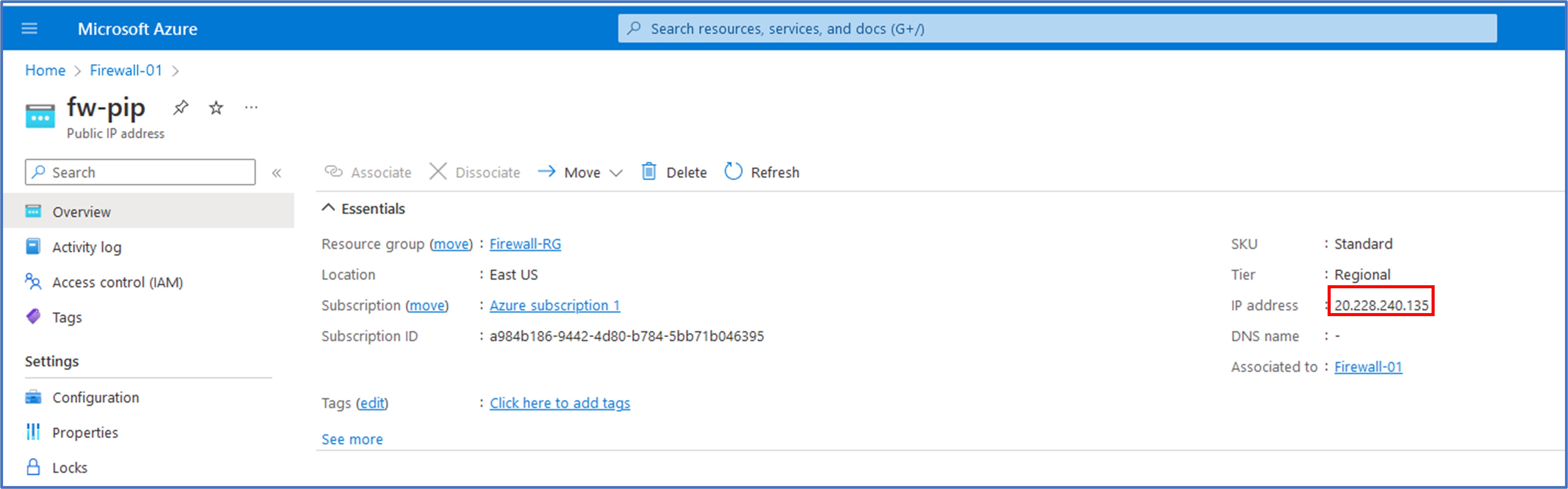
With the firewall deployment completed, I then clicked on “Go to Resource” to review some details about the firewall that will be needed for configuring routes on our next task. On the Overview tab, I noted that the private IP address assigned to the firewall was 10.0.1.4.
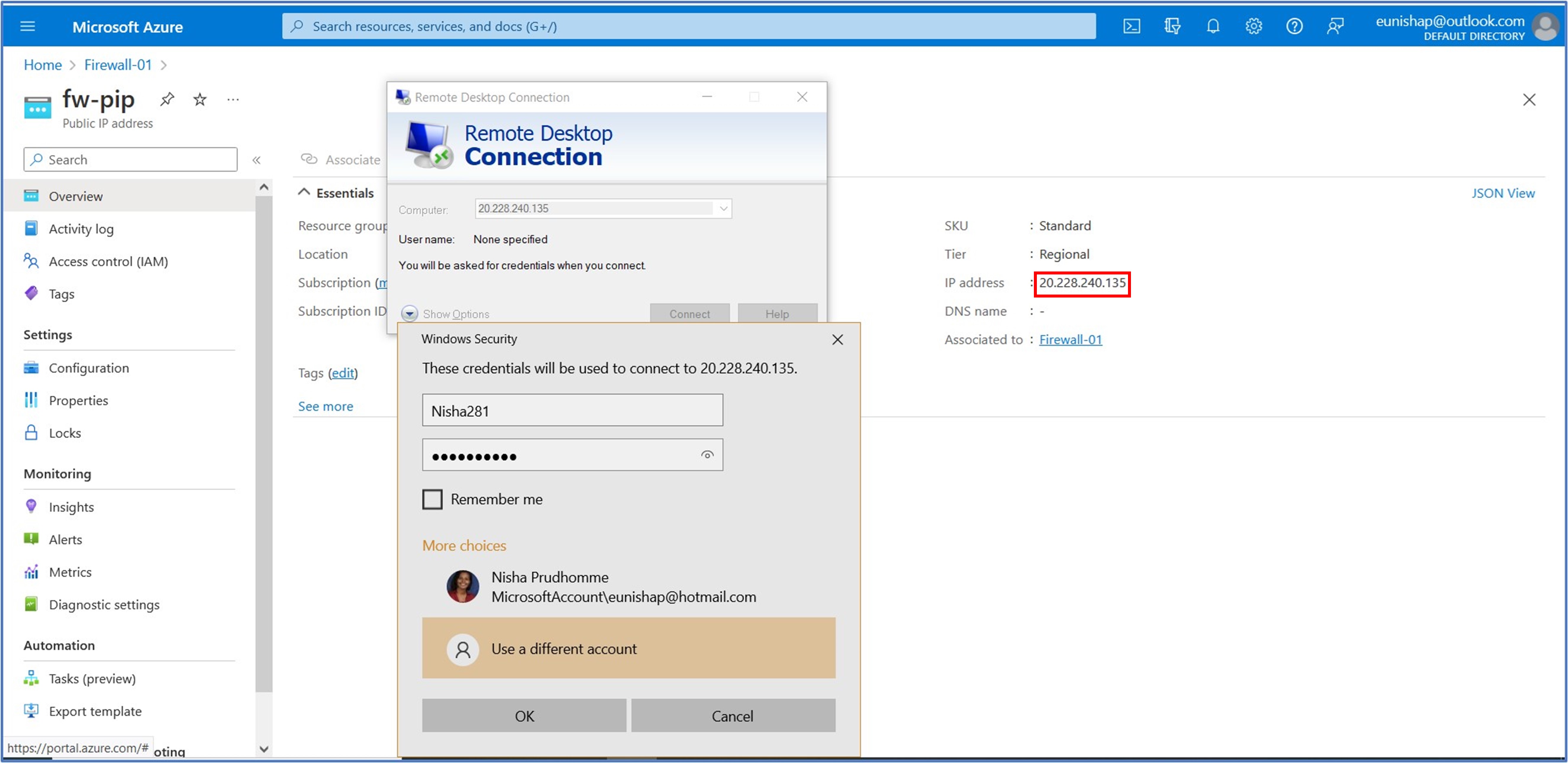
Next, I clicked on the name of the firewall’s Public IP to verify the assigned Public IP address, which was 20.228.240.135. This public IP address will be needed for initiating our RDP connection to the firewall from our PC during testing in a later step.
Task 5: Create a default route
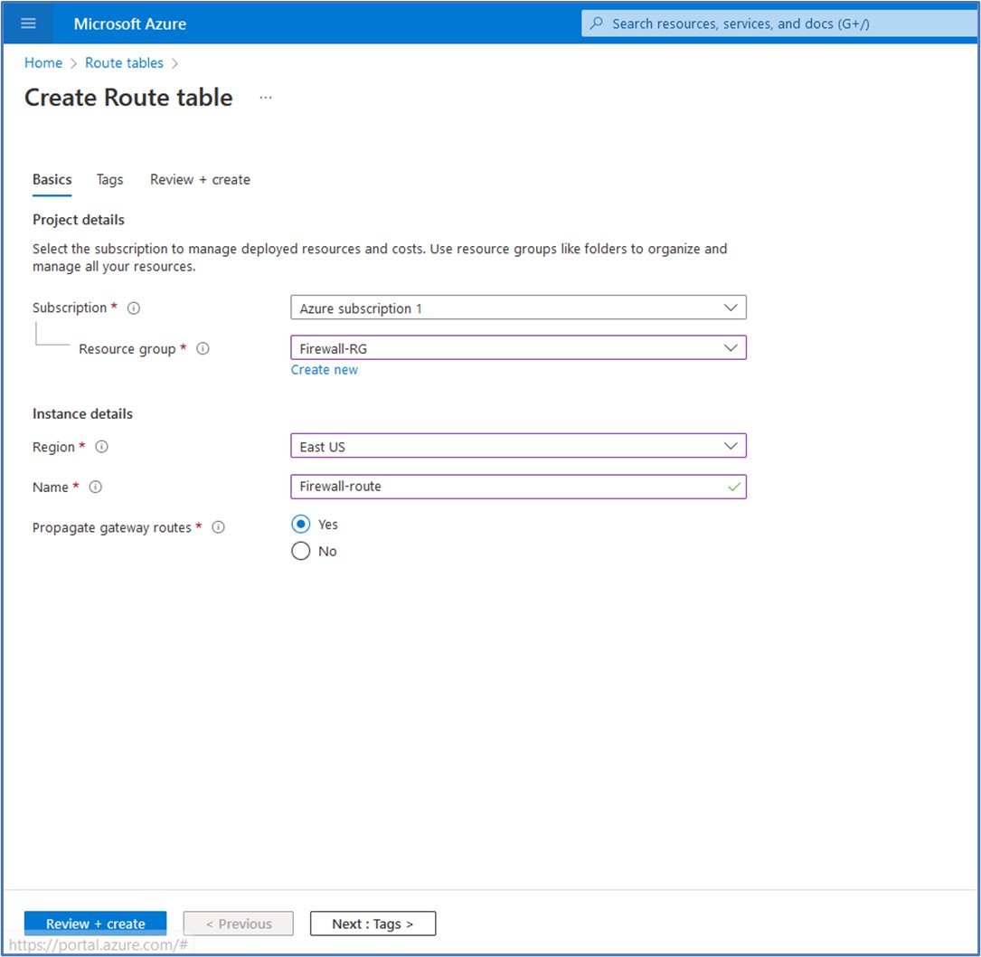
Our next task involves configuring a Route Table that will be used to store a custom route (User-Defined Route) that we need to configure for the Workload subnet. To create the Route Table, search for route table in the top search bar, select it from the list of services, then click on + Create. Here, we choose our Subscription, Resource Group, Region, and enter a name for the Route table. Next, I gave the instance the name of Firewall-route. Propagation of gateway routes option should be enabled if you plan to associate the route table to a subnet in a VNet that is connected to your on-premises network through a VPN Gateway and you want to propagate your on-premises routes to the network interfaces in the subnet. I could have disabled this option on this step because this is not needed since there is no VPN Gateway included as part of this deployment. Click on Review + Create to begin the deployment of the Route table.
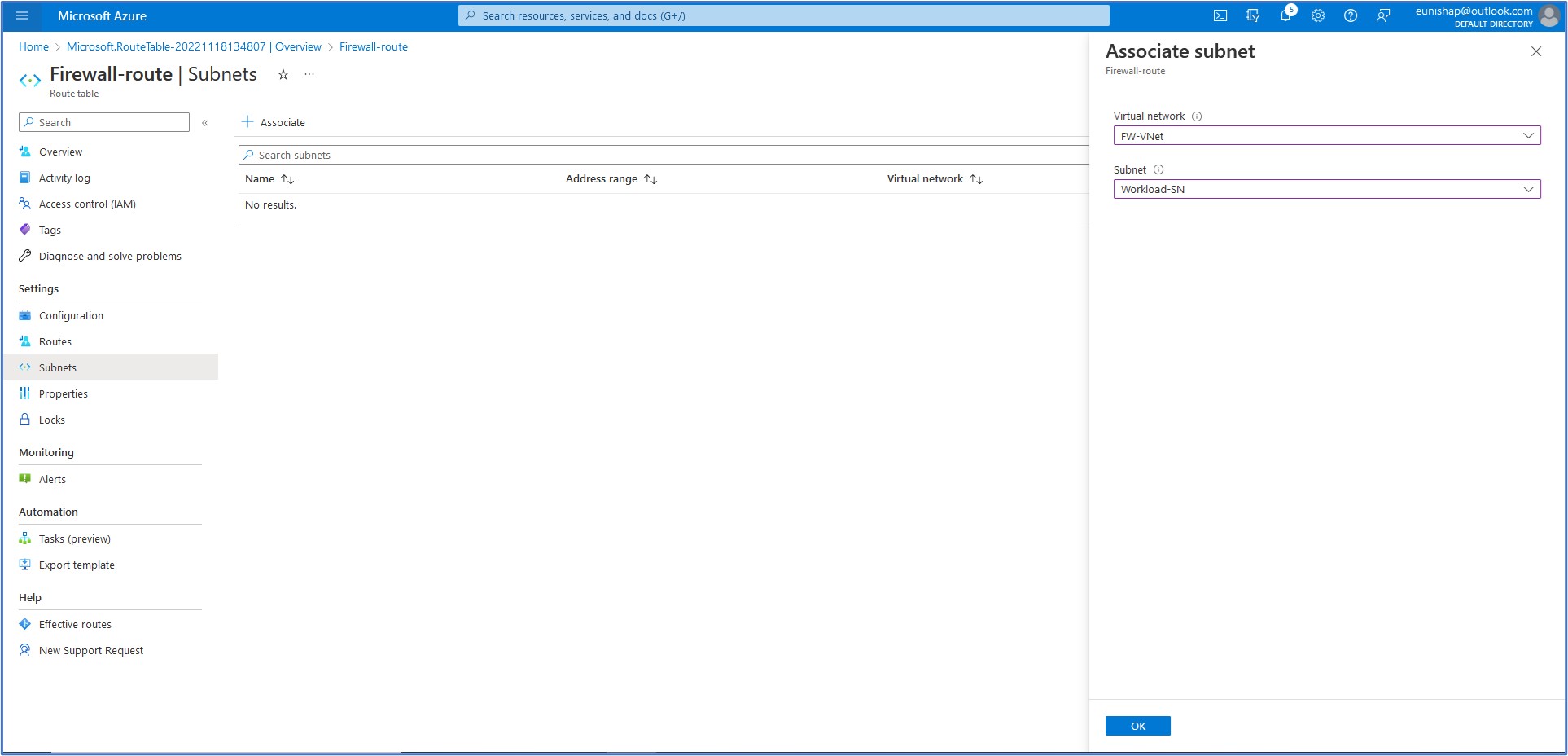
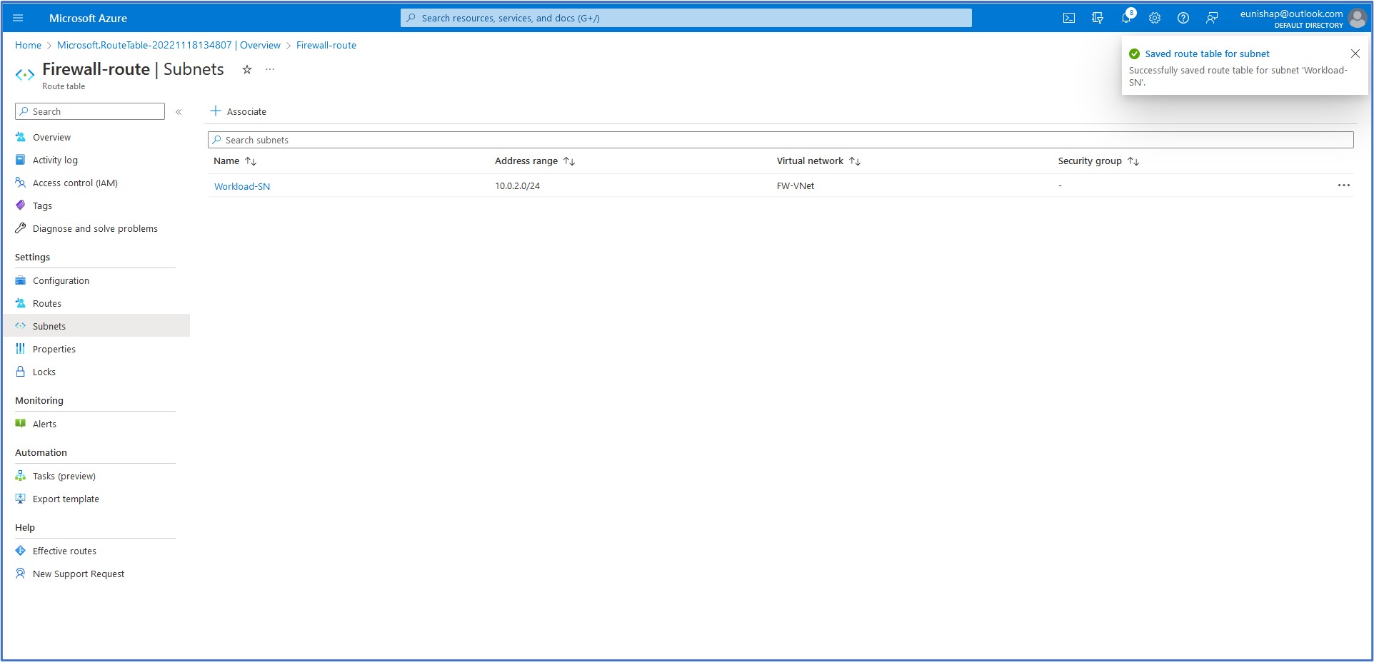
Now, creating a Route Table alone is useless without associating it to a subnet and adding custom routes to it. So in this next step, we will associate the new Route Table to our Workload subnet by searching for the Route Table in the top search bar, then select Route table from the list of services, then clicking on our configured route table to open it.
On the Subnets menu listed under Settings, click on + Associate to display the configuration pane that opens on the right. Here, we will select the Virtual network that we want to associate this route table with, FW-VNet. Then, select the Workload-SN for the next field entry for the subnet. Click on OK to accept this configuration
Task 3: Create a Default Route
On the Workload-SN subnet that is associated with this route table, we want to configure the default route to redirect outbound traffic to go through the firewall rather than allowing it to route directly out to the Internet. By doing so, we can ensure that the firewall rules that are configured within our firewall policy are applied to the traffic before making a decision to allow or deny the flow. We can configure this custom route by navigating to “Routes” under the settings section of the menu and then click on + Add to open the Add route configuration pane.
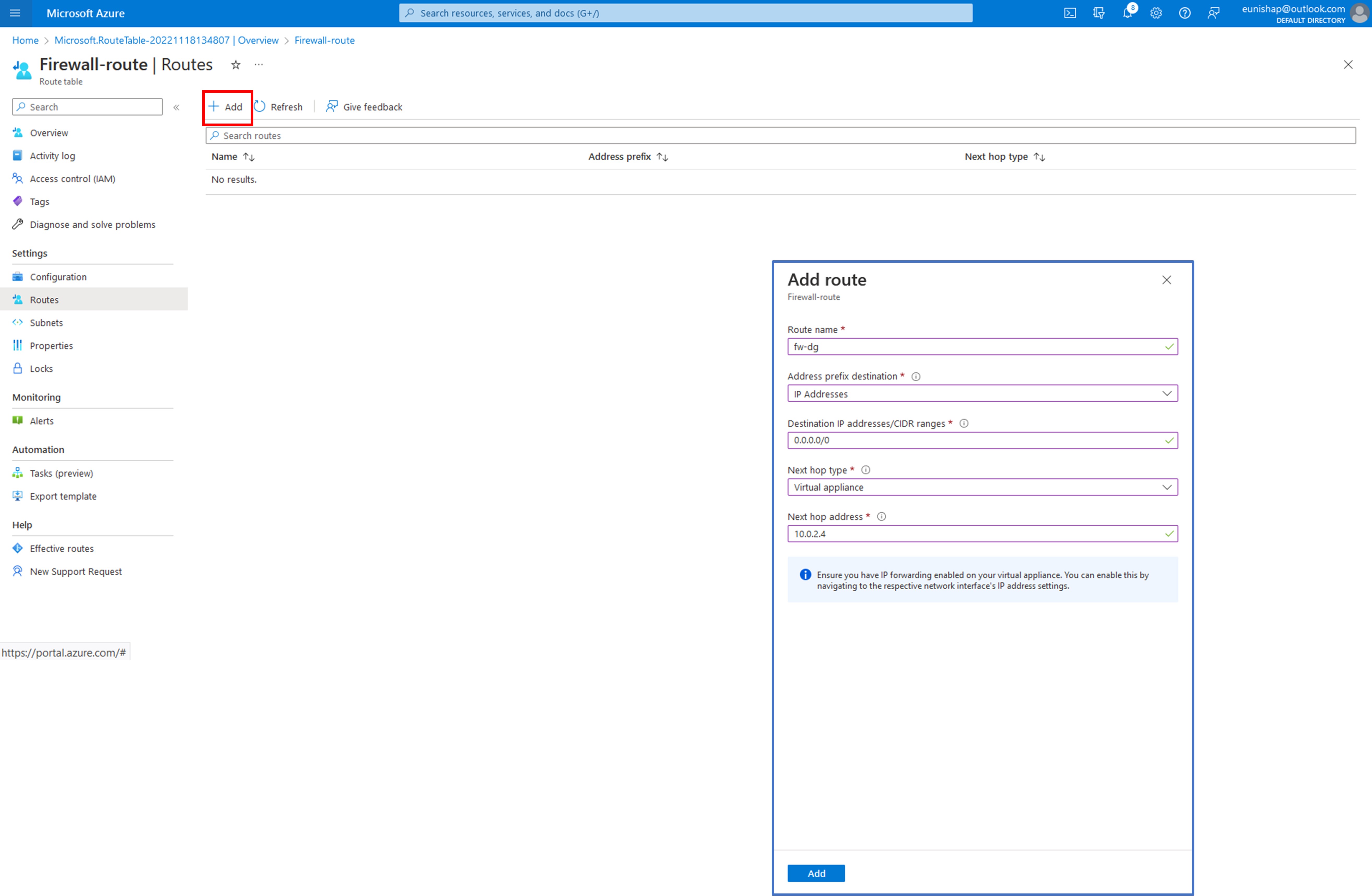
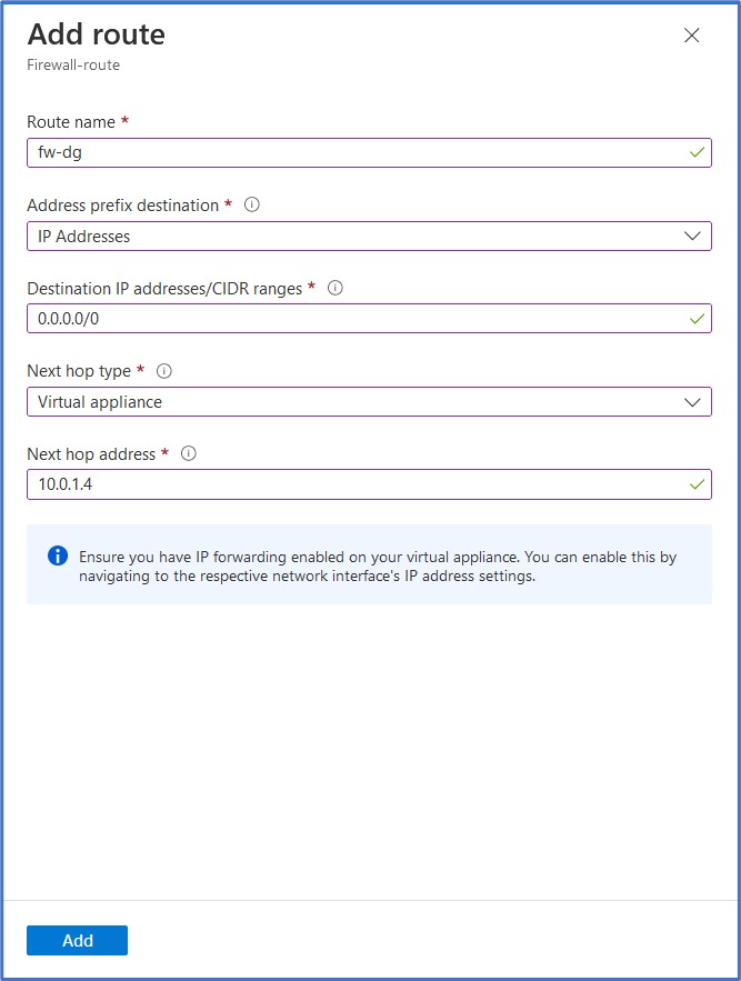
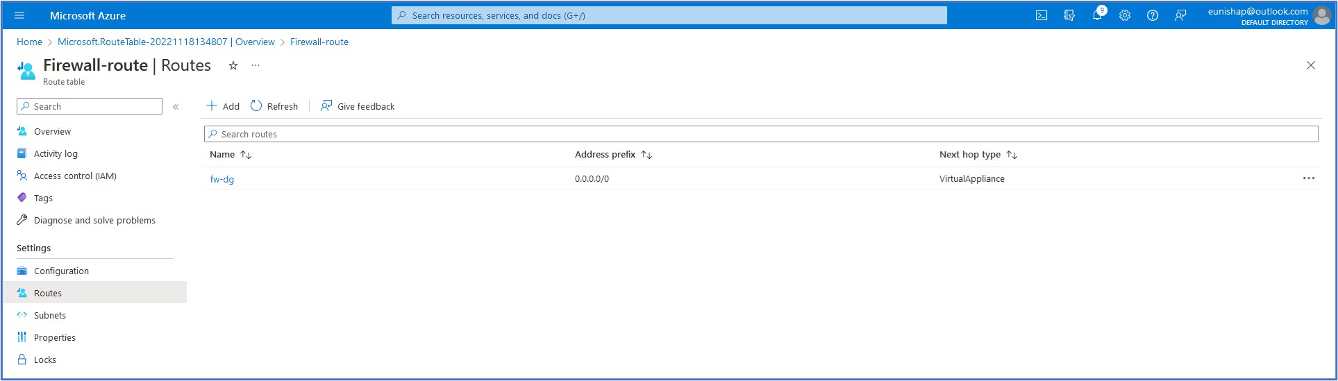
On the Add route configuration pane, we need to supply a name for the route (fw-dg) and an Address prefix destination. Here we must select an Address prefix destination of either IP Address or Service Tag. We will select IP Addresses for this option since we have a specific Destination IP address that we want to enter in CIDR notation for the default route of 0.0.0.0/0. Next, select the Next hop type from the drop-down list and select Virtual Appliance since we want all outbound Internet-destined traffic to be redirected to the firewall. Finally, we will enter the private IP address of the firewall as the Next hop address, 10.0.1.4. Click on Add to add this entry to the route table. The purpose of this custom user-defined route (UDR) entry is to override the System Default Route for this address prefix that is currently set to route all outbound traffic directly to the Internet.
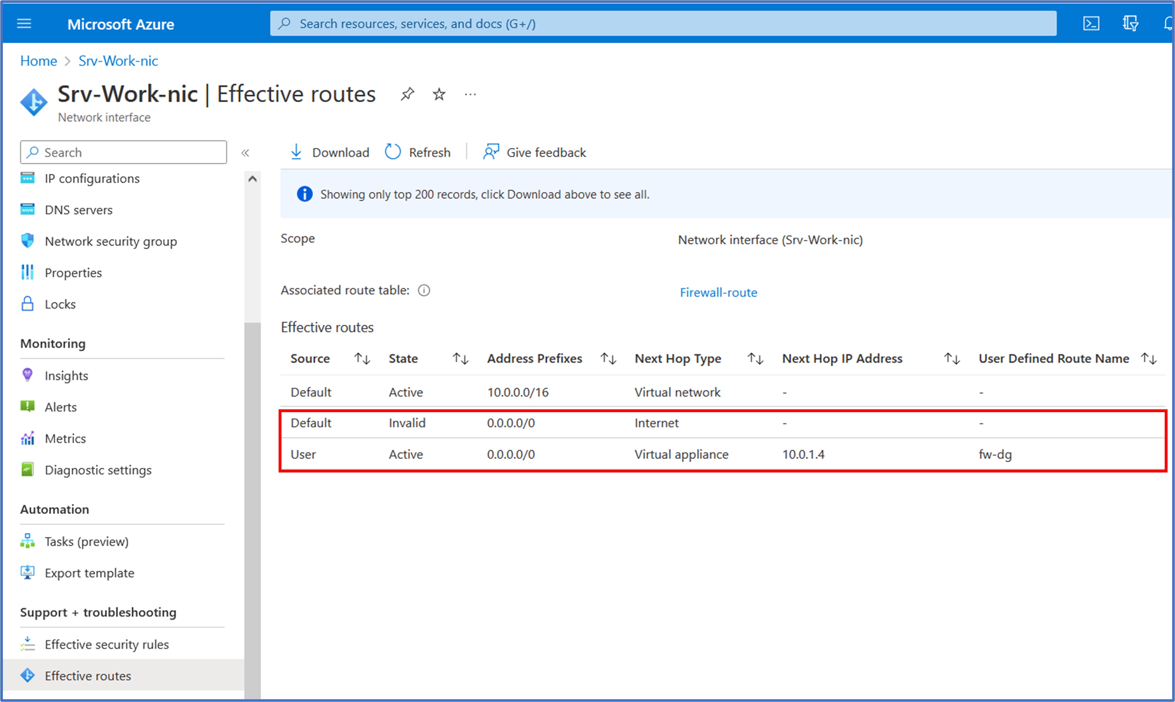
Let’s take a quick glance at the Effective Routes for the network interface of the workload server VM. We observe that the newly created UDR has now overwritten the System Default route that previously routed outbound traffic to the Internet. The Default route now shows a state of “Invalid” and the UDR is now the active route for the 0.0.0.0/0 address prefix. This is the expected behavior that we are trying to achieve such that outbound traffic will now be redirected to the firewall first to determine whether or not the Internet-destined traffic request will be allowed or denied after the evaluation of the configured firewall rules, which we will create in the next task.
Task 4: Configure an application rule to allow access to www.google.com
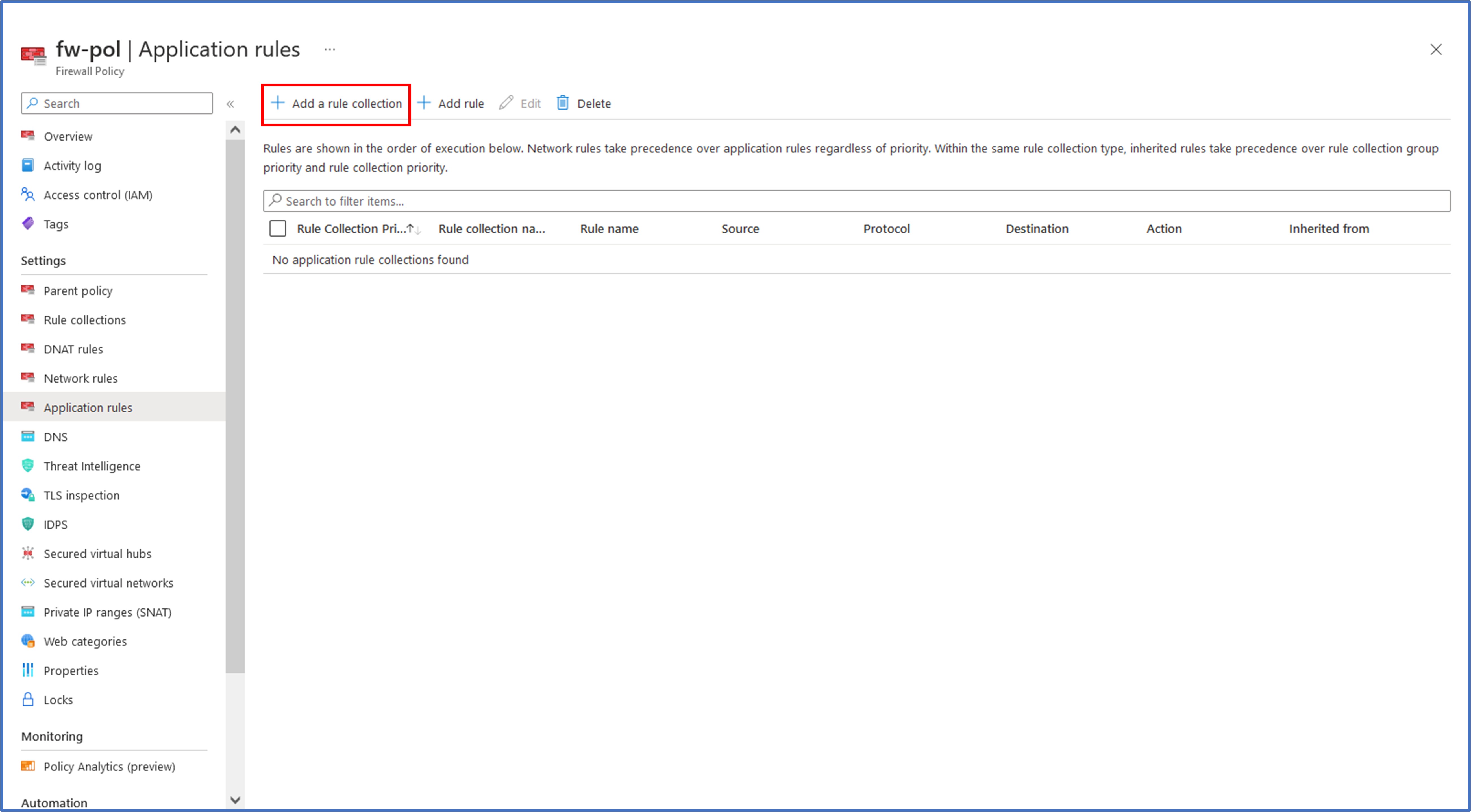
With the default outbound route now in place, it is now time for us to add firewall rules to our firewall policy to provide the desired action on the traffic received by the firewall. From the main menu, we can click on All resources and click on fw-pol to open the Firewall Policy resource.
The first type of rule that we will add is an application rule. For this task, we will add an application rule that allows outbound access to www.google.com. Under Settings, click Application Rules. Then click on the + Add a rule collection to begin the creation of a new collection where we can enter rules.
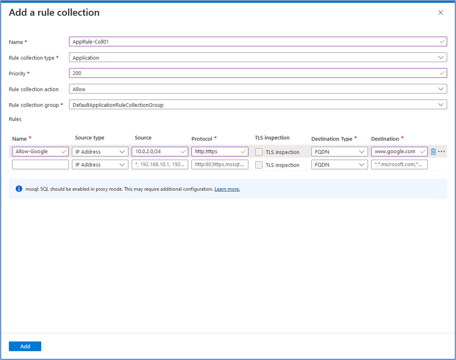
We need to enter some information for the new rule collection. Here, we will enter the following values:
Name: AppRule-Coll01 Rule Collection type: Application Priority: 200 Rule collection action: Allow Rule collection group: DefaultApplicationRuleCollectionGroupRule Next, we will enter the values for the new Application rule as follows:
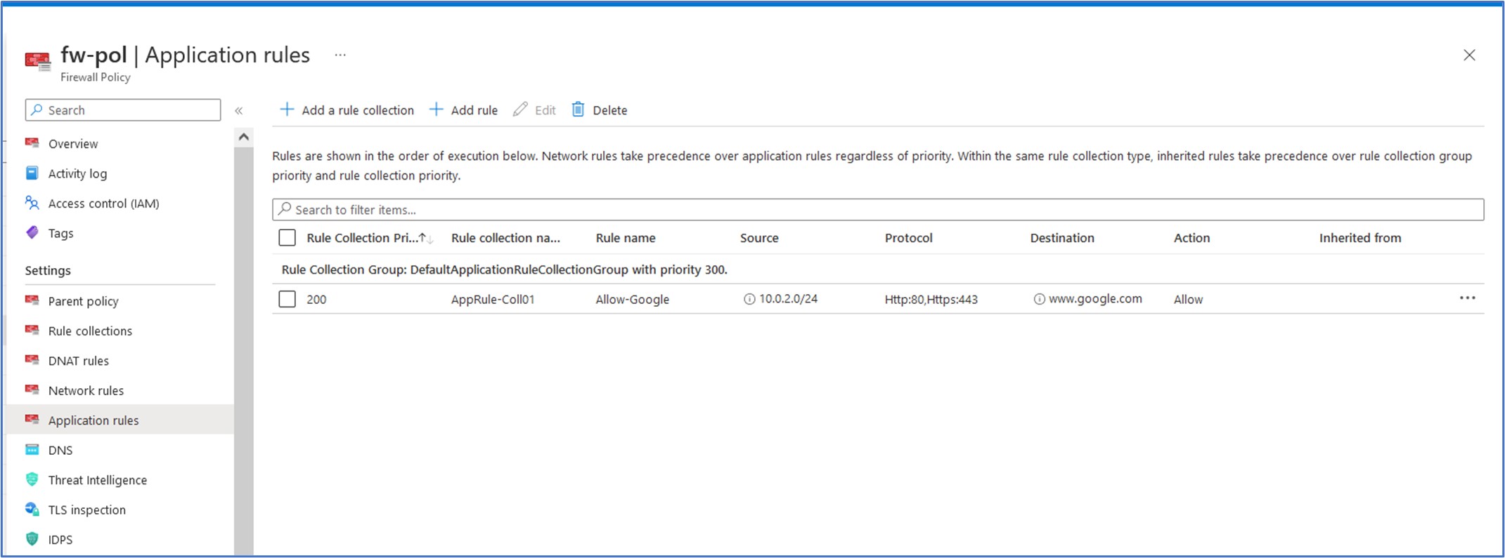
Name: Allow-Google Source type: IP Address Protocol: http, https Destination Type: FQDN Destination: www.google.com Click on “Add” to add this new Rule Collection and Rule to the firewall policy
Task 5: Configure a network rule to allow access to external DNS servers
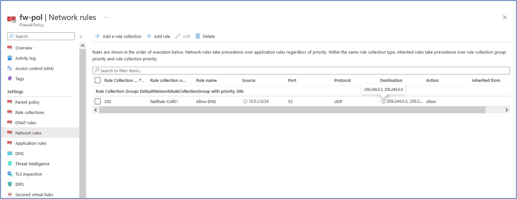
Now, we will configure a network rule that allows our subnet to have outbound access to two IP addresses at port 53 (DNS). This is needed so that any traffic that our firewall receives that is sourced from our workload subnet (10.0.2.0/24) will have access to communicate outbound with the two public DNS servers (Century Link DNS) for Public DNS name resolution. These DNS server IP addresses are 209.244.0.3 and 209.244.0.4.
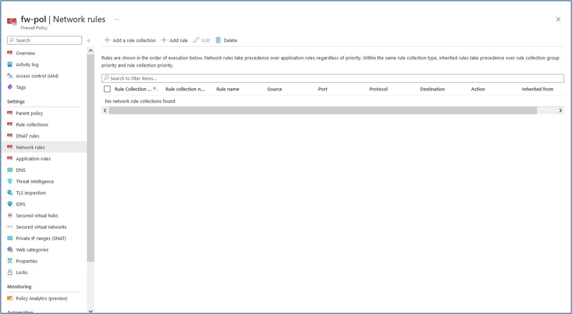
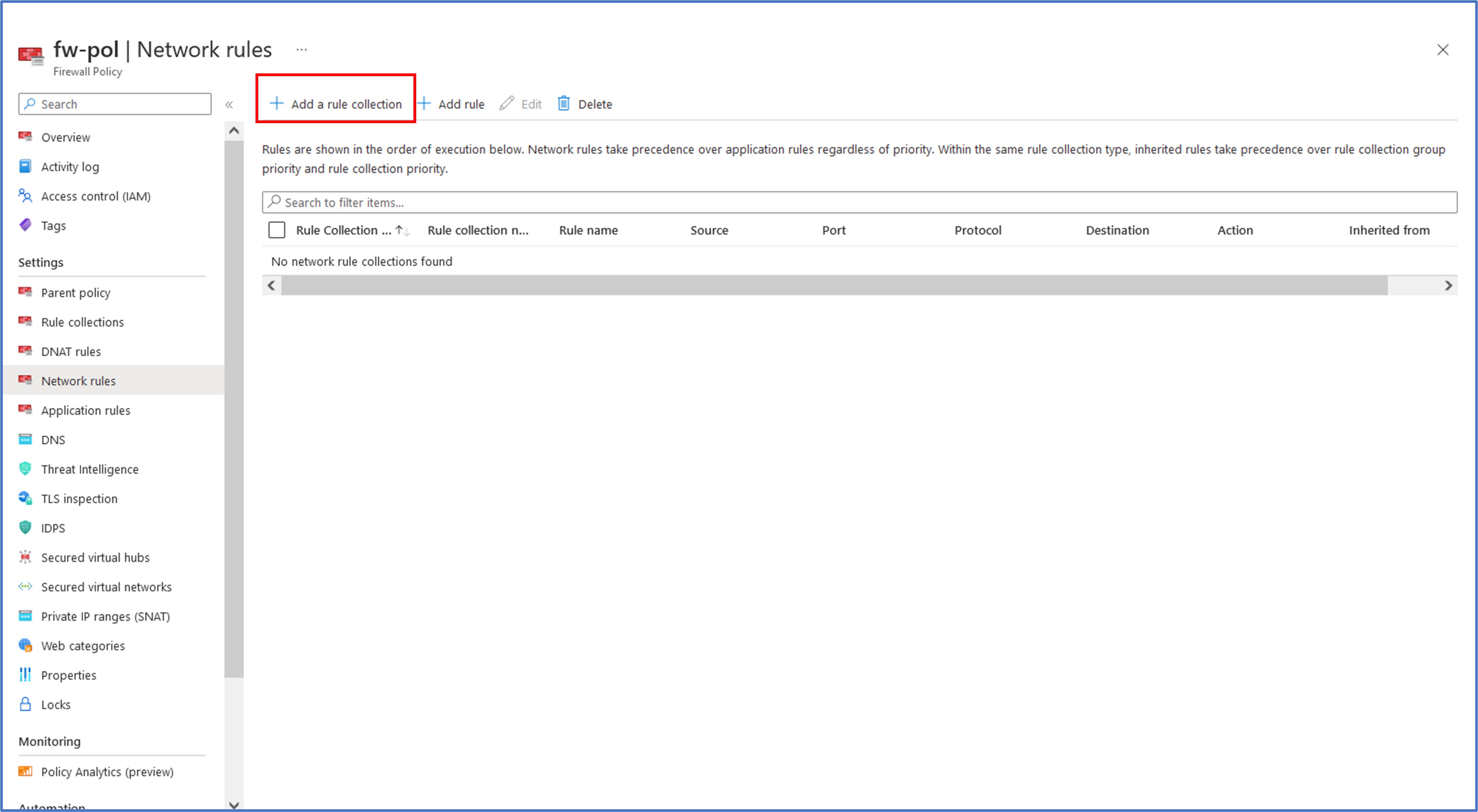
While on the firewall policy resource page, click on Network rules located under Settings on the menu and then click on + Add a new rule collection.
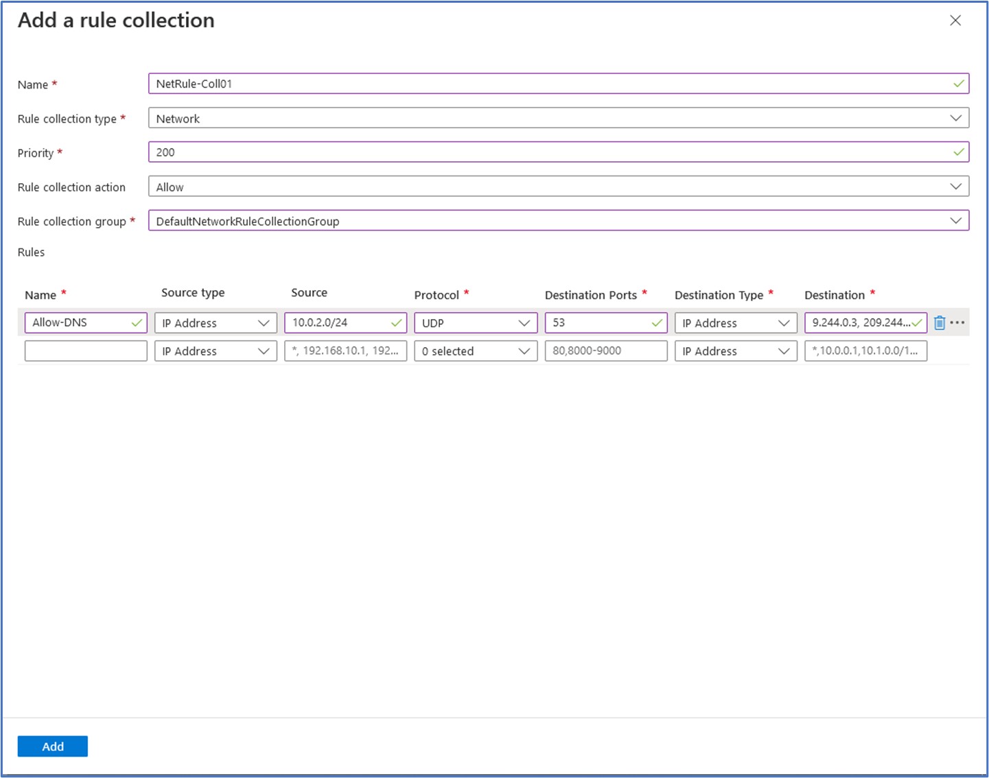
On the Add a rule collection window, we will enter the following values to configure this collection and network rule:
Name: NatRule-Coll01 Rule collection type: Network Priority: 200 Rule collection action: Allow Rule collection group: DefaultNetworkRuleCollectionGroup Next, we will enter the values for the new Network rule as follows:
Name: Allow-DNS Source type: IP address Source: 10.0.2.0/24 Protocol: UDP Destination Ports: 53 Destination Type: IP Address Destination: 209.244.0.3, 209.244.0.4
Task 6: Configure a NAT rule to allow a remote desktop connection to the test server
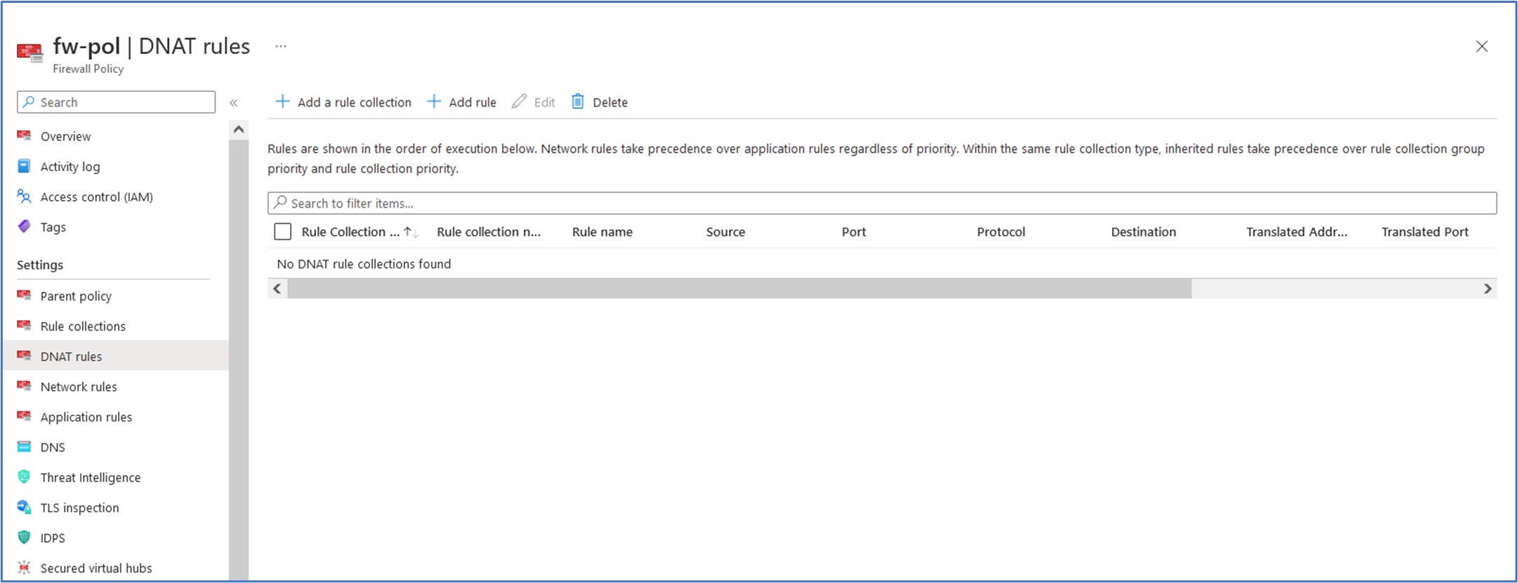
In this task, we will add a DNAT rule that will allow us to connect a remote desktop to the Srv-Work virtual machine through the firewall. We will begin by creating a new rule collection for our DNAT rules. While on our Firewall Policy resource page, click on DNAT rules located under the Settings section and then click on + Add a rule collection.
Next, we will enter values for our rule collection for DNAT as follows:
Name: rdp Rule collection type: DNAT Priority: 200 Rule collection group: DefaultDnatRuleCollectionGroup
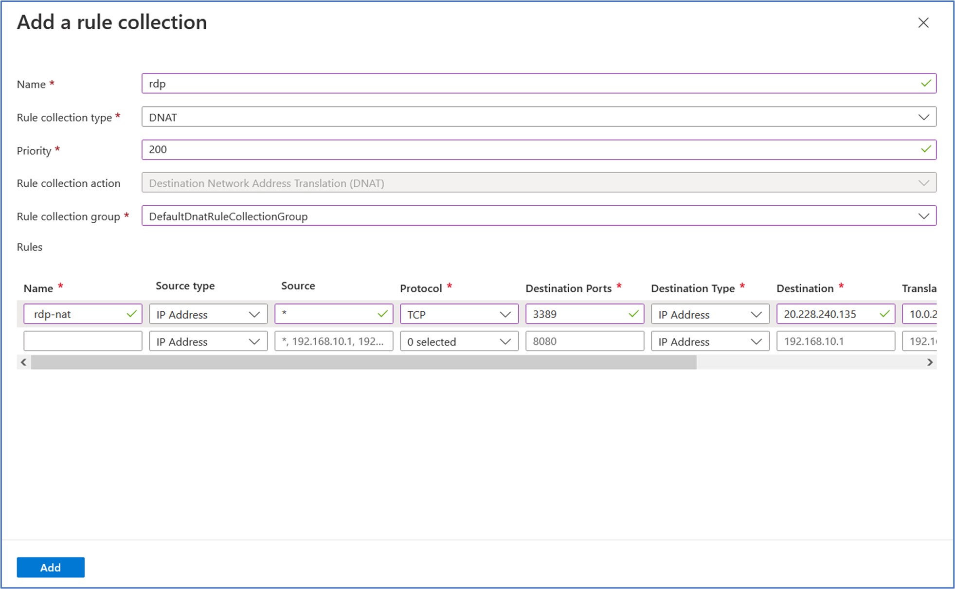
In the rules section, we need to enter values that will allow an inbound remote desktop connection to the workload server from any source IP address by going through the firewall.
We will enter the following values listed below for the Destination Network Address Translation (DNAT) rule to accomplish this such that any RDP connection made from any source IP address to the firewall’s public IP address (to port 3389) will translate to the private IP address of the workload server VM. That’s right! We want the destination IP address to be translated to the IP Address of the workload server VM so that we can connect to it through a remote desktop connection from another device.
Name: rdp-nat Source type: IP Address Source: * Protocol: TCP Destination Ports: 3389 Destination Type: IP Address Destination: 20.228.240.135 (this is the public IP address of the firewall) Translated address: 10.0.2.4 (this is the internal/private IP address of the workload server VM) Translated port: 3389
Click on Add to add this rule collection and DNAT rule to the policy of the firewall resource. It will appear similar to the following:

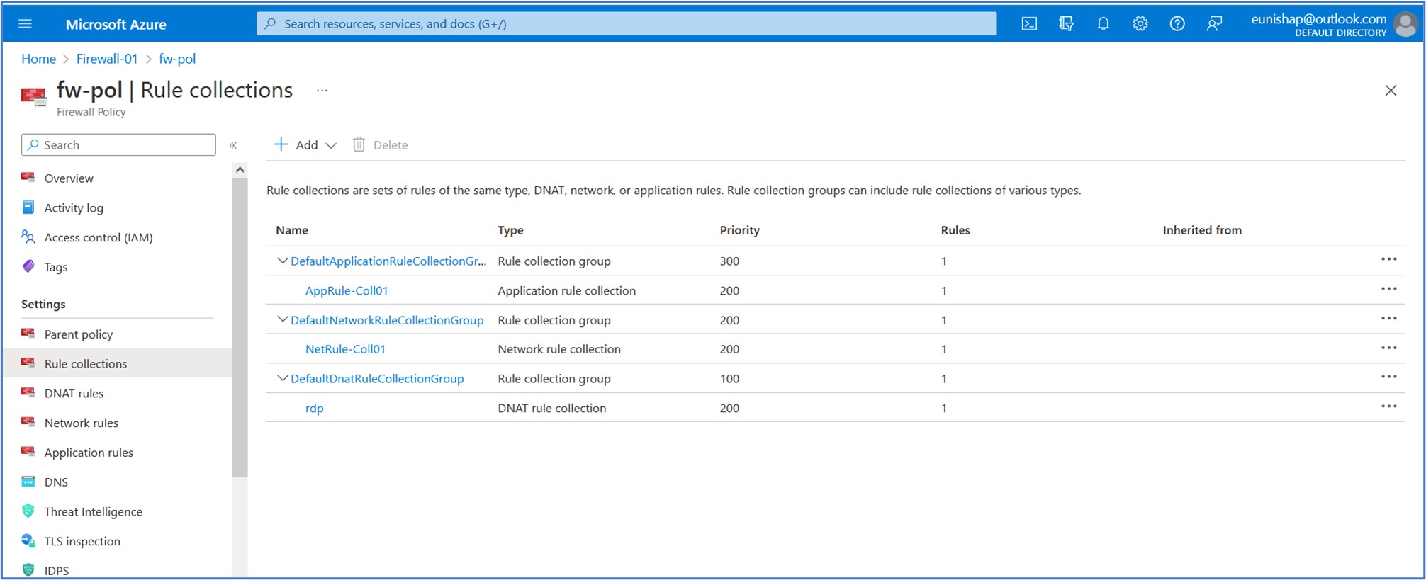
We can view each of our configured rule collections by clicking on Rule collections under the Settings section of the firewall policy resource.
Change the primary and secondary DNS address for the server’s network interface
For testing purposes in this exercise, we will configure the Srv-Work server’s primary and secondary DNS addresses with custom addresses. We can do this by navigating to the network interface of the Srv-Work virtual machine. Under Settings, select DNS servers. Under DNS servers, select Custom. Type 209.244.0.3 in the Add DNS server text box, and 209.244.0.4 in the next text box. Click on SAVE to accept the new settings.
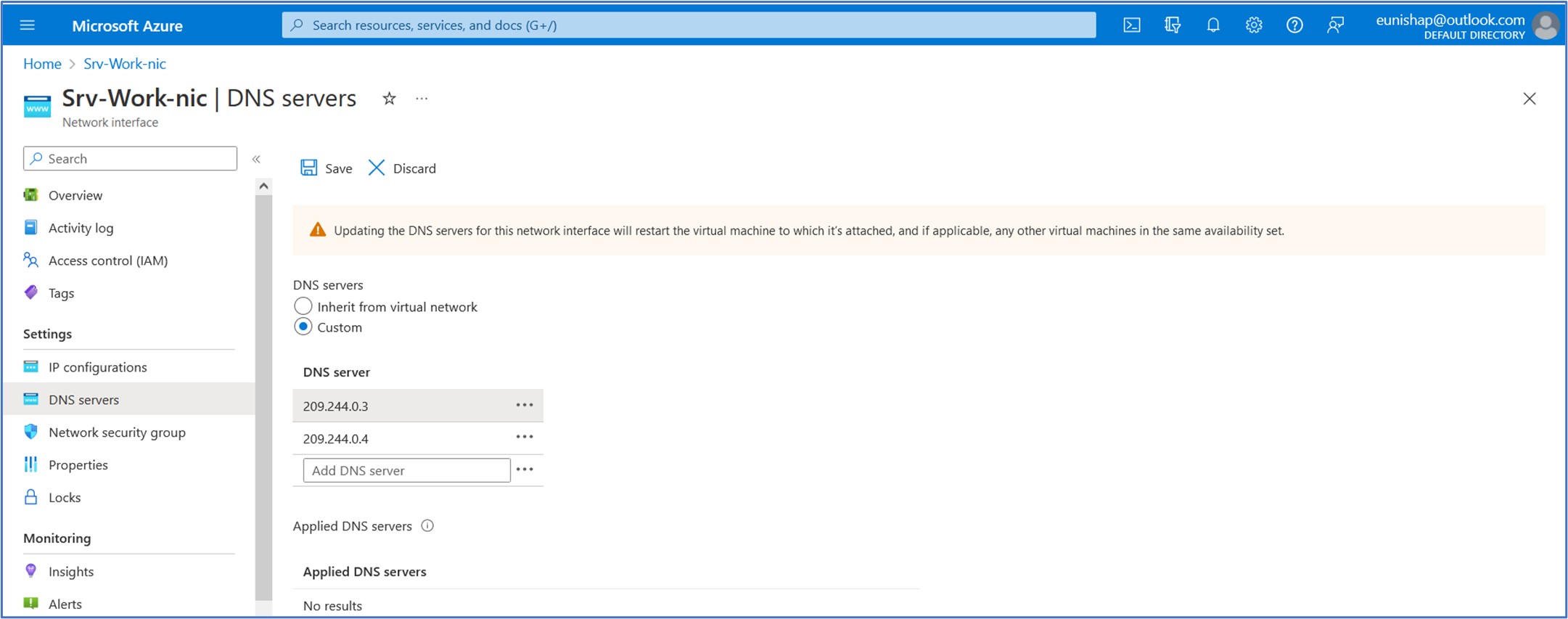
Clicking back into the configured DNS servers page, we observe at the bottom of this screen that these settings have been applied to the NIC of the Srv-Work virtual machine.

Task 7: Test the firewall
Finally, it is time to test the firewall rules that we have configured for this deployment. We will begin by launching the Remote Desktop Connection tool from our PC. We will enter the public IP address of the firewall, in my case it is 20.228.240.135. On the prompt, enter the admin account credentials that you configured when you deployed the workload server VM, then click on OK.
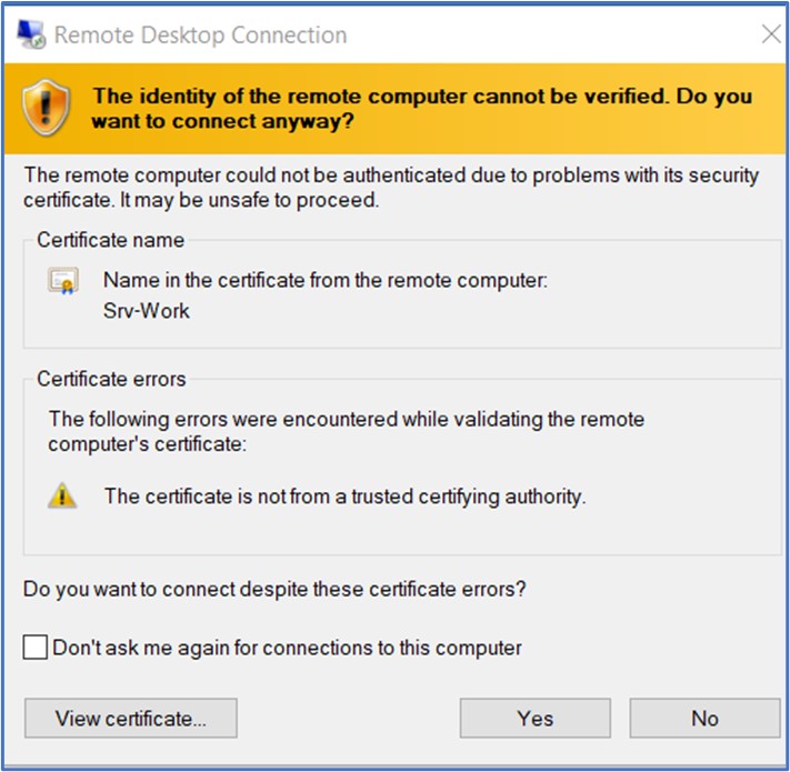
Next, you will be prompted about a certificate for the workload server VM, Srv-Work. Click on “Yes” to proceed. A successful connection to the workload VM proves that our configured DNAT rule is working as expected and is translating our firewall’s Public IP address to that of the internal/private IP address of the Svr-Work VM.
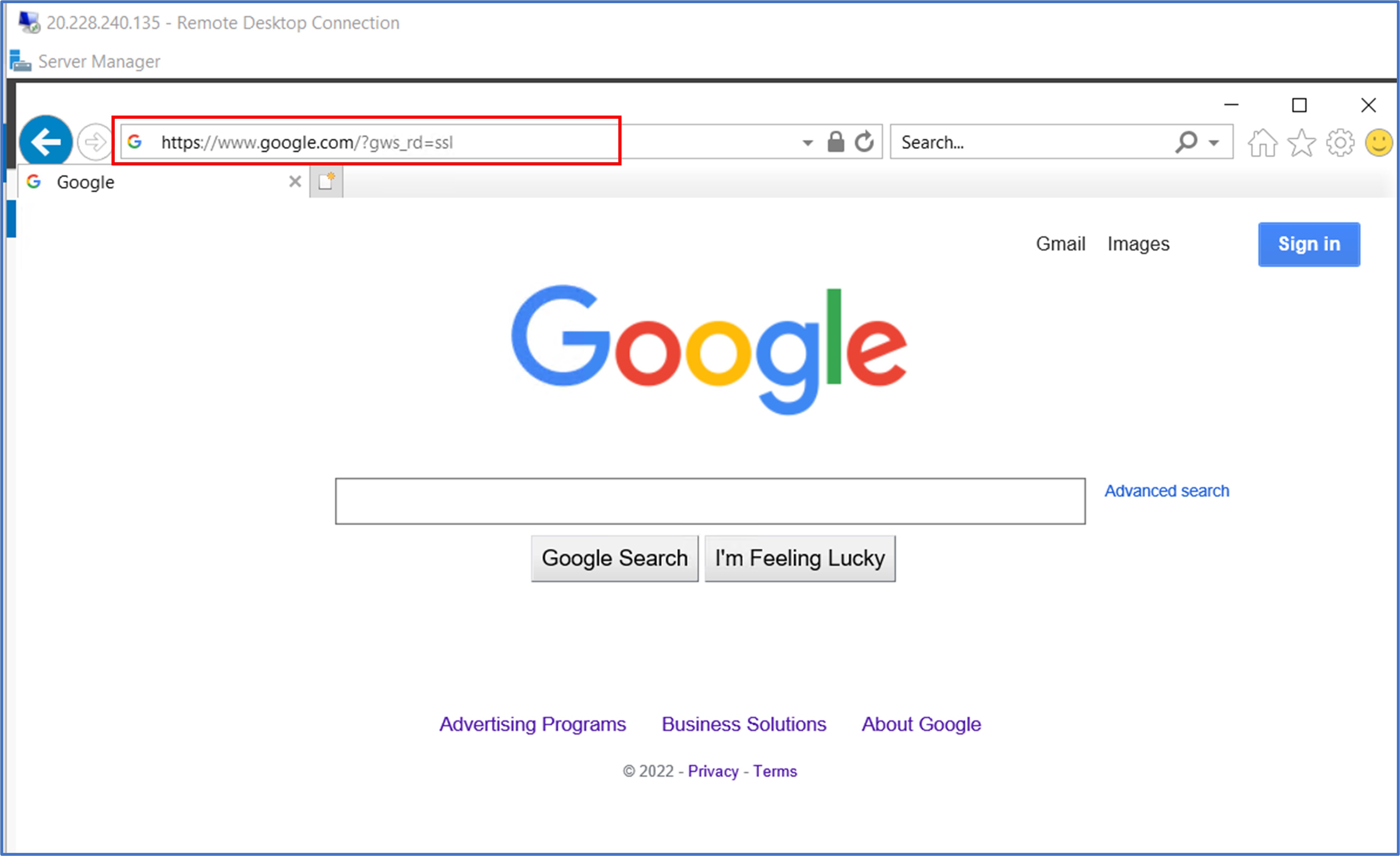
Once we are logged into the Srv-Work virtual machine, we need to launch the web browser so that we can test whether or not we will be permitted to access www.google.com site. Here, we can see that the firewall rule worked as expected to allow this communication. Remember, anything that is not explicitly permitted by a rule will be denied by default when using a firewall. The Application rule that we configured for Allow-Google is allowing this outbound traffic to Google.
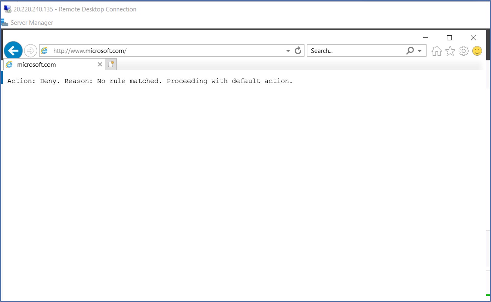
In this next test, I tried to navigate to www.microsoft.com in the web browser and was presented with the following feedback. This connection was denied by the firewall because we did not configure an explicit rule to allow connections from our subnet to communicate with this FQDN.
This concludes the demonstration on how to deploy a firewall policy with rules for allowing or denying outbound traffic from Azure. Please stick around for more because I have more firewall labs coming up in my next few articles!
Thank you for reading!
References: